Gormanston Index
Tweezer Methods
|
|
|
|---|
|
Gormanston Index Tweezer Methods |
The Gormanston Tweezer,
|
|---|

The source of this design was a zany 'brainstorming' session at the Gormanston Summer School in 2003. John Pollard and myself are good at bouncing ideas off each other and the gibbering banter that occurs has produced some very fruitful, usable ideas. For those that are not accustomed to the brainstorming process, I should explain that it can happen with two or more people and the objective is to explore any and all possibilities about something that is perceived as a problem. No holds are barred and nothing should be considered too stupid to be thrown into the discussion.
The tweezers currently available are generally rather unwieldy, too heavy and have a spring effect that is too strong for delicate manipulation of a queen's sting. Many conventional tweezers are also rather longer than really needed.
Length was considered, John showed a small pair of tweezers that were only about 40 mm long and made from thin springy metal strip, these were light and delicate, but still had more resistance to closure than would be comfortable.
|
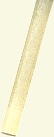
I introduced John to 'pultruded' fibreglass rod that is available for making model aircraft and kites, this material is light and yet stiff without being brittle and is available in thicknesses in the region of one to several millimetres in diameter. The material is made by pulling a bunch of parallel glass fibres through a die that also acts as an extrusion die for the resin. This die is usually at one end of a heated tunnel that cures the resin as the rod is pulled through, hence the name 'pultrusion'. The operations required for manufacture of this unusual tool can be performed using a Dremel type grinding tool. The sample rod shown at right is 2.0 mm in diameter and is rather too stiff for our purpose, however a similar material between 1.0 mm and 1.5 mm diameter will 'give' enough for our tweezer if the limbs are around 100 mm in length. I have executed the drawings to indicate a rod diameter of 1.4 mm diameter. |

|

|
|---|
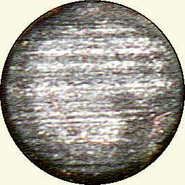
The view at extreme right is of the cut end of the sample rod, but I am afraid the definition is not as good as I had hoped (I will replace it with a photomicrograph when I get the opportunity).
We decided on this material for the limbs of the tweezer and sought something to make the delicate tips that are required. Sewing needles were suggested, but considered likely to damage a sting as the contact pressure of two fine cylindrical surfaces could be quite high. John suggested opposing one needle with two, only to immediately point out that a needle had an eye which already consisted of two parallel members. Thus the basis for this design was conceived and has taken almost a year of further thought to put down in this form.
In a description such as this, it is difficult to lay out the stages in a precise order, because some of the actions involved depend on the needles and materials available as well as the tools and cutters that you may have already in you toolkit. It is probably best to start by making the steel tips first, but bearing in mind the way that these will ultimately be fitted into the legs of the tweezers.
The diagrams and photos on this page are rather larger than life size and in various degrees of magnification, in order to show the significant details of the various parts.
The 'business end' of the tweezer is formed from a darning needle or sewing needle that has a basic diameter of about 0.7 mm, such needles are available in lengths varying from about 50 mm up to around 75 mm and a certain amount of 'selection' will be required as the eyes are formed by swaging and can be somewhat variable in form. By the time you have finished reading this description you should be able to make the necessary judgments.
This huge picture of a needle eye shows the sort if imperfections that can be present in a finished and polished sewing needle... Check both sides as there can be considerable differences in eye profile on either side. (The eye itself is formed in a 'sort of' punch and die and the steel flows unevenly under the immense pressures.)

The needle requires to be cut into two portions, however these should be unequal in length, The pointed portion has an inherently lower resistance to being pulled out, simply by virtue of it's shape. This is why we have drilled the extra hole in one of the limbs and most of the depth of this hole needs to be added to the length of this portion. The reason I have used the word most rather than giving a precise measurement is that our finished tips will not be quite the same length, as the single tip will nest just inside the curvature of the outer end of the eye.
![]()
Before you can establish this cutting position more precisely, I will have to detail the other preparations that will be required on our metal tips.
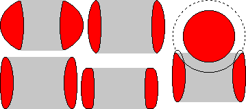
The cross section through the eye is not quite ideal, I show some typical cross sections at rather large magnification along with an 'ideal' profile, at extreme right below. The dotted line around the straight limb is a clearance of 0.14 mm to take account of the diameter of a queen's sting and shows the effect that the polishing action should achieve.
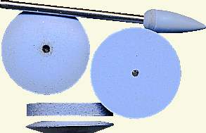
The eye needs polishing to a smooth 'spoon' shape. The diamond impregnated rubber grinding discs (below left) are ideal for this purpose.

|

|
|---|
|
This polishing serves two purposes, it removes roughness and reduces the contact pressure that can be exerted on the sting, which in turn reduces the chance of damage to the sting by pinching onto sharp edges. (The drawing exaggerates the penetration of the disc though the eye, but it shows the way the disc is applied to the eye.) |

|
|---|
|
Final polishing of the eye was done with a cardboard disc combined with 'Autosol' chrome polish... The needle eye should appear something like this after the polishing operation. |

|
|---|
The cut end of the eye section should have any burrs removed and the end roughly rounded. The portion of this end that will be in the groove of the pultruded rod, requires scoring heavily on its surface, using a very thin grinding disc in order to provide a key for the epoxy adhesive that we will be using.
The point itself should be also be heavily abraded in the same way over all of the surface that will be within the groove and hole.
|
|
Now for the limbs themselves...

The above drawing shows a nominal 100 mm length of suitable pultruded rod with a 2.5° chamfer at one end, which gives a 5° spread between the legs of the finished tool. This arrangement may still be too stiff for comfortable use, but a method of reducing the stiffness will be described lower down on this page.
The two legs are first formed into a pair by epoxy resin adhesive (Araldite - normal, not the 5 minute type) using suitable clamps and a flat surface. After this glueing operation the legs will look like this...

You can use a honey warming cabinet to accelerate the curing of the epoxy resin, which both speeds up the process and improves the physical strength of the joint.
|
|
This pair of legs can be relieved on the inner surface of each leg to reduce the stiffness. The relief should be carried out over as long a length as possible without encroaching on the 15 mm or so at the end that will be used to fix the metal tips. The red area in the drawing below shows the area that should be relieved and it should be stressed that the relief must leave an even thickness of material remaining in order to spread the stresses equally over as long a length as possible.

|
The un-chamfered ends require a groove about 10 mm long, on the inner face that will accept the metal tips that have already been described. The grooves should be cut using a Dremel tool. One of these grooves will require a drilled hole about 0.3 mm diameter to extend it As shown in the lower sketch. The depth of the simple groove should be slightly less than the diameter of the needle shank so that the thread that will be used for binding will have a positive action in retaining it in place. The depth of the groove in the drilled version should be slightly less deep than the other and should be judged according to the profile of the pointed end of the needle. |
|
|---|
After reducing the limb thickness and mounting the cut portions of the needle using epoxy adhesive the tweezer would look something like the drawing below when compressed to the operating position.
![]()
To finish off our tweezer we should wrap each end with thread in a similar way to the other end. This wrapping can be done at the same time as the insertion and gluing of the metal end pieces and should be tight. The wrapping should be smoothed and glazed with adhesive in the same way as before. In order that we may render the tweezers smooth and unlikely to carry contamination, a coating of liquid epoxy should be applied over the entire surface (apart from the active portion of the metal tips). This final part of manufacture can only take place after the epoxy is cured. The liquid epoxy is available at aero modeling supply stores. The fully finished item is shown below.

Another type of tweezer suitable for picking up and manipulating honey bee eggs will be described on a separate page in due course. It will be based on similar production methods.
|
|