| |
|
|

|
Live CD version
|

|
|---|
| |
|
|---|
Woods' Apidictor, Electronic Listening Device For BeesInformation
regarding the Apidictor has been absent from this website for several
years. There is constant interest in the device and little information
elsewhere, so what is here is an important resource. I have located
much of Dave Cushman's material and displayed it in what I think is
close to the original form. I have not altered much, mainly repairing
links or deleting those that link to other websites that no longer
exist. The electronics enthusiast will see that Dave didn't complete
this project and there are a number of gaps. If anyone is able to fill
them please let me have details and I will make changes. All additional
material or corrections will be easily identified with the original
left intact.
Roger Patterson. 13th Dec 2012
The late Eddie Woods developed a listening device with filters that could detect
the changes in sound produced by a colony before and during swarming.
|
|---|
More recently Rex Boys wrote a book
"Listen to the Bees" which deals with the original
equipment (it is the copyright of Beedata.com so is not reproduced here).
With the advent of digital and op-amp techniques it should
be a simple matter to take this work further.
This page will analyse the original and propose some modern experiments that I
hope some of you, younger, electronic design engineers will take up and build modern
alternatives.
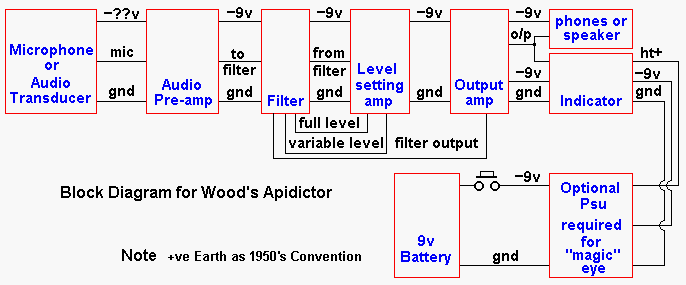
Block Diagram
Block interface specifications of Apidictor
In order that different individuals and groups may update or repair original items of
equipment I will stick as near as possible to the original specification with suggestions
for modern equivalents.
- gnd
- Is battery positive, and chassis metalwork.
- -9v
- Is the nominal battery voltage of Eddie's transistorised versions mk4 & mk5. It is
not critical, but if we use it then it helps compatibility of new and old "spare
parts" and allows defunct parts to be replaced by up to date modules.
- -??v
- This negative voltage is a sub rail from the 9v battery and is heavily decoupled. It is
used in the original purely in the pre-amp, but I have included it here in case it is
required by any electret microphones or other active listening devices.
- mic
- In the original a crystal microphone was used, but we will merely specify a high
impedance voltage output which will then be compatible with the pre-amp input no matter how
the audio signal is actually derived. The signal voltage would be in the region of 0.5v pk
with a 2 megohm source impedance.
- to filter
- This is the pre amp output (at the moment guessed at) of around 1v p-p @ 10k impedance.
- from filter
- The filter output is capacitively coupled to a level setting amplifier.
- full level & variable level
- Are switch connections that are ganged with the filter switching enabling the volume
control to be by-passed so that hiss listening is at full volume.
- filter output
- Is the resulting signal (either full volume or the set level) which is then capacitively
coupled to the input of the final output amplifier.
- o/p
- The headphone output (thought to be 600 ohm), the same signal is also passed to the
indicator.
- ht+
- The magic eye used in the original would have required about 150v - 180v on it's anode
to function, this was derived from a small transistor oscillator. (I will clarify this when
I track down the original data). The indicator could very easily be replaced with an array
of LEDs, which gets rid of the requirement for the high voltage rail.
The Original Schematic
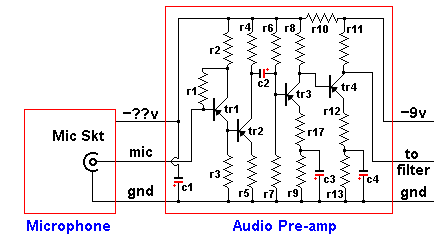
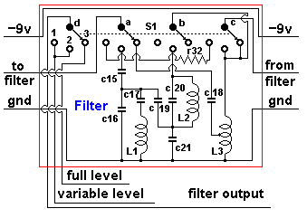
Has been broken down into the same blocks that are represented in the block diagram. All
component values are listed in the table further down the page.
| |
These two portions of the block diagram above, have been grouped
together as any new designs will treat this as one single block.
It is simply a microphone and amplifier whose output is
about 1v peak to peak.
The original used a crystal mic, but I will be offering versions using
moving coil and electret elements.
|
|---|
|
The previously published circuit diagrams identified the switch positions
wrongly.
This has been corrected here, in addition the resistor that gives
"straight through" operation in position one, has been labeled r31.
The switch wafer order has been re-arranged, but each wafer still
performs it's original duty.
| |
|
|---|
| ITEM | MK 4
VALUE | MK 5
VALUE | NOTE |
|---|
| c1 | 50µf | | 22µf - 100µf acceptable |
| c2-c7 | 10µf | | |
| c8 | 0.1µf | 1µf | |
| c9 | 25µf | | 22µf ok |
| c10 | 100µf | | 63µf - 220µf acceptable |
| c11 | 1µf | | between gnd & V1 cathode on Mk 5 |
| c13, c14 | 2N2 | | |
| c15, c16 | 33N | | |
| c17 | 41N2 | | various capacitors in parallel to make up value |
| c18 | 2N2 | | |
| c19 | 5N5 | | various capacitors in parallel to make up value |
| c20 | 4N4 | | 2 x 2N2 in parallel |
| c21 | 51N4 | | various capacitors in parallel to make up value |
| r1 | 2M2 | | |
| r2 | 47K | | |
| r3 | 220K | | |
| r4 | 33K | 15K | |
| r5 | 4K7 | | |
| r6 | 220K | | |
| r7 | 22K | | |
| r8 | 33K | | |
| r9 | 4K7 | | |
| r10 | 22K | | |
| r11 | 10K | | |
| r12 | 2K7 (nominal) | | Adjust on test, see note xx |
| r13 | 10K | | |
| r14 | 150K | | |
| r15 | 68K | | |
| r16 | 220R | | |
| r17, r18 | 470R | | |
| r19 | 2K7 | | |
| r20 | 68K | | |
| r21 | 22K | | |
| r22 | 100R | | 0.5 watt |
| r23 | 47K | | |
| r24 | 10K | | |
| r25 | 33K | | |
| r26 | 150K | | |
| r27, r28 | 220K | see note yy | |
| r29 | 100R | | 1 watt |
| r30, r31 | 22K | | |
| r32 | 68K | | could be 100K trim pot see note zz |
| tr1, tr2 | OC 202 | OC 702 | |
| tr3, tr4 | AC 107 | NKT 226 | |
| tr5 - tr11 | OC 71 | NKT 224 | |
| L1 | 18H8 | | |
| L2 | 40H8 | | |
| L3 | 7H | | centre tapped |
| D1 | OA 85 | | |
| rv1 | | | |
| V1 | VM 160 | | |
| T1 | ?? | | hand wound, to be sorted |
| S1 | 3 pole 4 gang | | |
| S2 | push to make | | toggle will be ok when the battery drain is reduced |
Winding details for the chokes and transformer are available, but
not to hand at the moment. Simple op amp filters will be suggested in replacement anyway.
Principle
History
1941,1946,1951,1964,
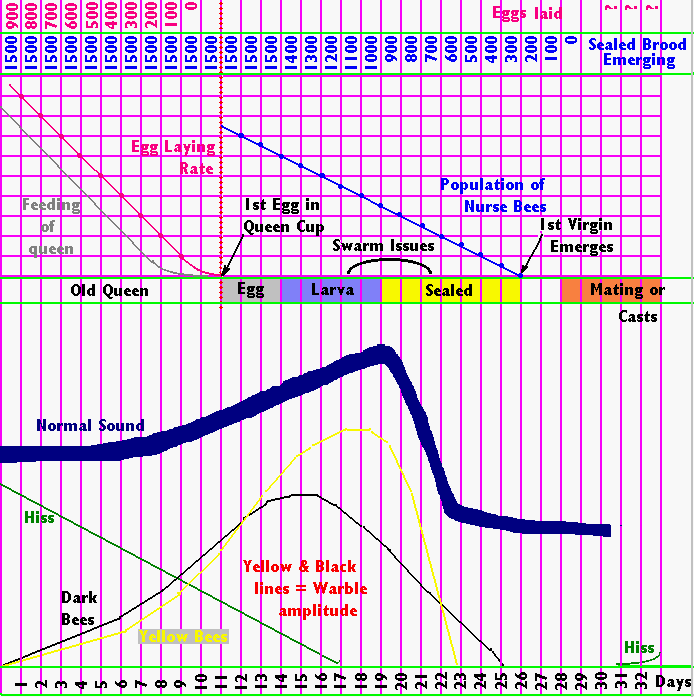
The queenless "roar" or "moan"
Eddie's Graph
Indicators
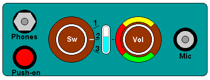
Apidictor Panel Layout (Mk4 & Mk5)
| |
The original panels were laid out like this. With the smaller, modern components
we can reduce the size considerably.
As I have done this analysis I have come to understand the device
fairly well. I am prepared to help (via Email only) anyone who is
experiencing difficulty in rebuilding or repairing one of these units.
|
|---|
this page is fragmented at the moment as it is under construction,
SOME OF THIS DATA MAY BE WRONG OR INCOMPLETE AT THE MOMENT
Printed from Dave Cushman's website Live CD version
Written Summer 2000,
Revised... 01 October 2001,
New Domain... 06 April 2004,
Upgraded... 25 October 2005,
Further Upgraded... 14 November 2007,
Source Code last updated...
|

|

|
|
|---|
|


